

Avoid Fan Traps in System Diagrams

A fan trap in data modeling occurs when multiple 1:N relations are joined on the “1” side, resulting in information loss. To the uninitiated, this is easiest understood by example: imagine a university with many colleges, each with many departments, which in turn have many professors. If modeled incorrectly, where the professors are given 1:N relations with colleges instead of departments, the result is a fan trap:
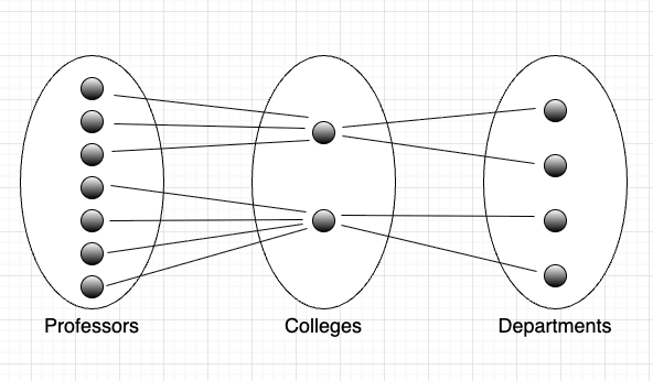
These relations aren’t wrong per se, but the mapping of professors to departments is lost. The resulting data modeling diagram looks like two hand fans joined at the narrow end, hence the name.

A similar problem can occur in system diagramming. When diagramming relations between resources in a system, information can similarly be lost when relations flow through an intermediary resource. In this article, we’ll look at a couple of examples of this problem and three potential fixes.
Fan Traps in System Architecture Diagramming
Fan traps are common problems when diagramming event-driven architectures. The defining characteristic of such architectures is that resources communicate via events. Events are typically routed through an event broker, which temporarily stores them until they are ready for consumption. This architecture has the added benefit of decoupling the resources, since they no longer communicate directly.
When diagrammed, a (highly simplified) event-driven system might look like so:

The similarity to fan traps in data modeling should be evident at a glance. The relationships between the message-producing resources (on the left) and message-consuming resources (on the right) are lost because they collapse at the center of the “fan” (the event broker). The diagram implies each producer communicates with all of the consumers, even though this may not be the case:
The same problem can emerge when diagramming communication paths in a network:

In the (again highly simplified) networking diagram above, node-to-node communications across the network fan out and back in through firewalls, resulting in specific communication paths being lost.
Solution 1: More specificity
One potential solution is to add smaller, discrete resources within the intermediate resource that the edge resources can connect through. In the event-driven architecture example above, adding “topics” allows us to differentiate the communications going through the event broker:
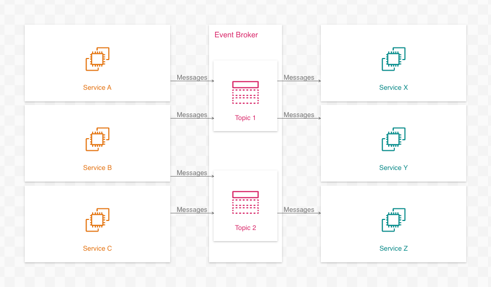
With the addition of topics, the individual communication paths can now be discerned:
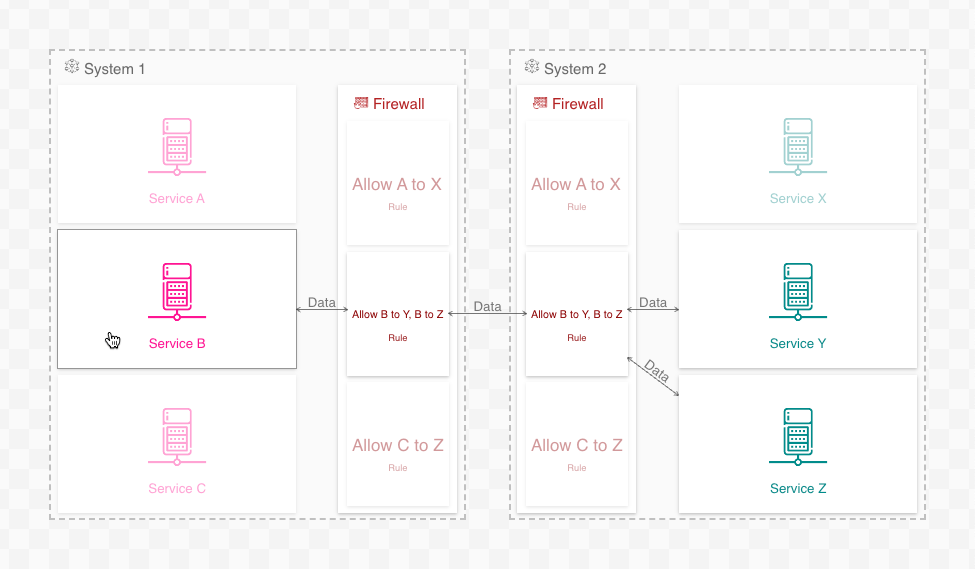
In the networking example, adding firewall rules to the firewall accomplishes the same:
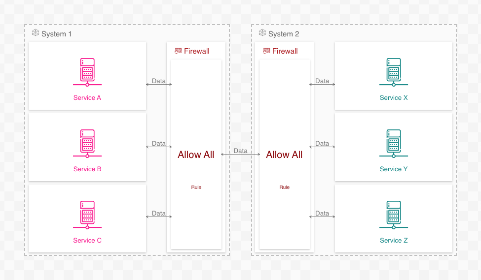
This solution is not foolproof, however. If, for example, the firewall rules are too generic, then the connections will remain ambiguous:
Furthermore, it is sometimes impossible or impractical to disambiguate connections via intermediate resources. Adding “The Internet” as an intermediate resource between all communications best demonstrates this:
Solution 2: Pass-through arrows
Adding additional intermediate resources to disambiguate communications is extra work that may not resolve the issue, even when feasible. A second, possibly better, solution is to add pass-through arrows to the intermediate resources:
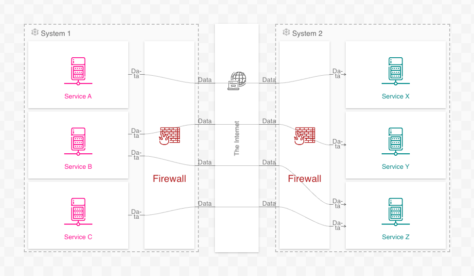
Pass-through arrows retain connections between edge nodes through intermediate resources without the need for added resources:
Pass-through arrows require less work and yield simpler diagrams than adding detailed intermediate resources. The trade-off, naturally, is less detail.
Solution 3: Do nothing
Before disambiguating relations with additional resources or pass-through arrows, consider the diagram’s goal and target audience. Depending on the viewer’s perspective, fanned-out relations may not even be a problem.
If the goal is to show the paths of actual communications between resources, then disambiguate the relations. Software engineers, architects, and SREs are likely interested in this information.
Conversely, if the goal is to show potential communication paths between resources, consider keeping the diagram as-is (i.e., with fanned relations). Network and security engineers, especially, would want to see this perspective on the system.
Questions or comments? Please reach out to me on LinkedIn or by email at billy@ilograph.com.