Better AWS Architecture Diagrams: Distributed Load Testing
Amazon Web Services (AWS) provides a vast library of practical solutions to common business problems. In this series, we focus on the architecture diagrams included in these solutions and attempt to expand and improve on them. Read the previous entry here. This article has been updated.
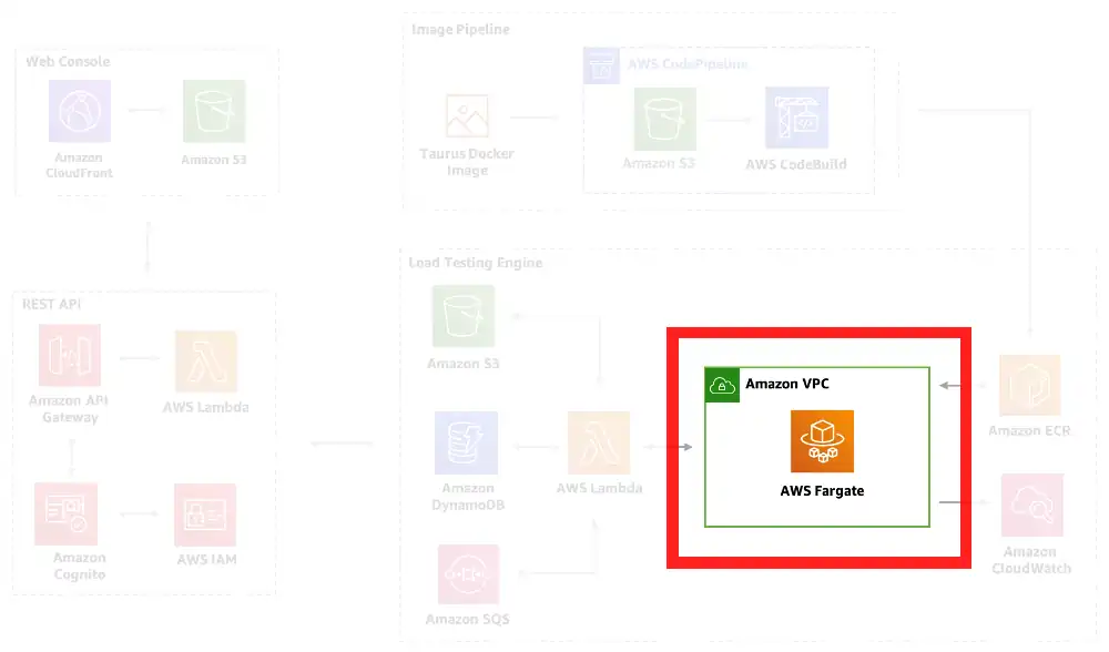
Below is AWS’s architecture diagram for their Distributed Load Testing on AWS solution. It comes directly from the linked repository. While the solution is excellent, the architecture diagram accompanying it exhibits a number of problems that limit its use as a technical resource.
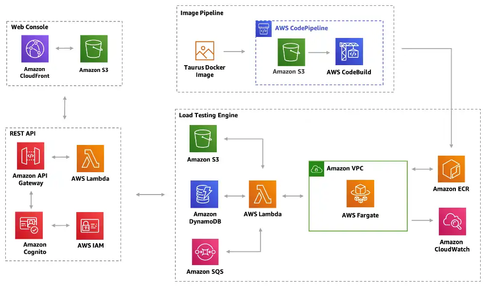
This diagram has some common issues (see the previous entry in this series) and a few new ones:
- The diagram lacks a clear purpose. It is referred to simply as an “Architecture Overview” in the solution.
- There are no named resources; only AWS Services (e.g. Amazon S3) are shown. Looking at this diagram, a viewer has no way of knowing what buckets, lambdas and other resources exist or how they are related.
- All of the arrows are unlabeled. The exact nature of the relations between these resources is a mystery.
- The diagram mixes run-time and deployment-time concerns.
- The diagram is missing critical details about security and access management.
In short, this diagram makes an impression, but fails to truly inform the viewer. This would be acceptable for a decorative element in a blog post or presentation, but as a technical resource, it can be much better. In this article, we remake this diagram with an aim toward creating a valuable source of information in its own right.
Like last time, we split the original into multiple perspectives, each focused on a single goal. We’ll have nine perspectives in total. Four will show static relations between the solution’s resources. The remainder show sample workflows (e.g. creating a new test, or canceling a test) with detailed control flows between the resources. We’ll start with one of the most important perspectives, run-time dependency:
Perspective 1: Run-time Dependency
Goal: Show which resources depend on which resources at run-time
Original
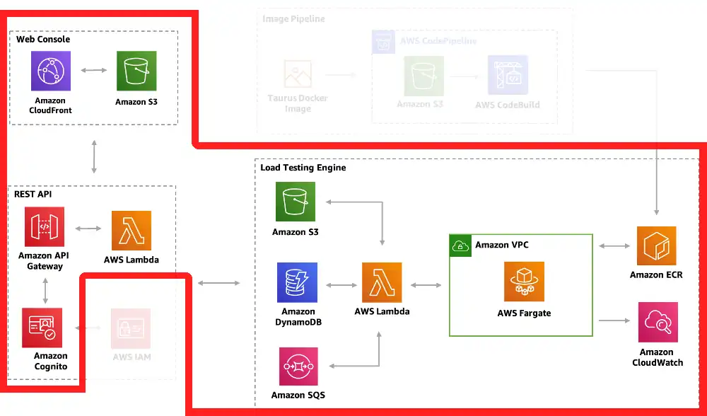
We address the issues in the original head-on. The perspective uses real resource names, and the relationship arrows are labeled. We’ve removed deploy-time concerns (e.g. CodeBuild) to focus on run-time concerns. And we’ve added detail about the testing console, including screen names and their API dependencies.
At first blush the diagram is much busier than the original; however, we can select a resource and see both what resources depend on it and what resources it depends on:
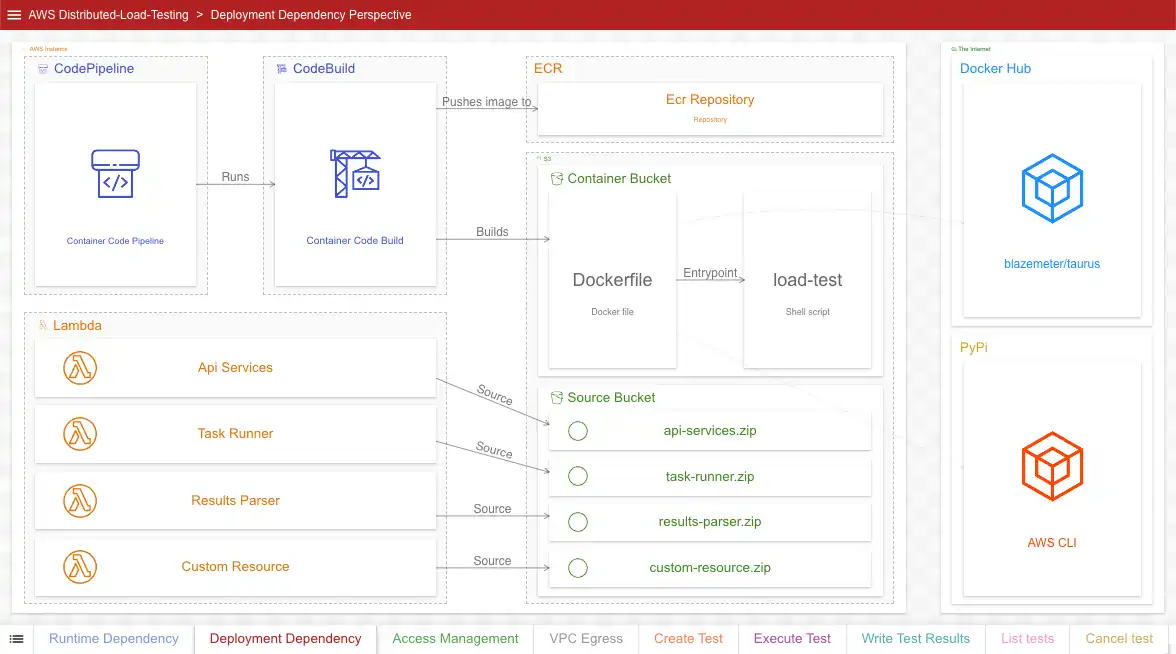
The aforementioned deploy-time dependencies are not truly gone, we’ve just moved them to a different perspective:
Perspective 2: Deploy-time Dependency
Goal: Show which resources depend on which resources at deploy-time
Original
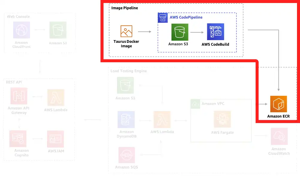
This perspective’s goal is identical to the last one, only it is focused on deploy-time dependencies. Note that this includes external dependencies (a Docker Hub image and a PyPi library). It also shows source code dependencies for the lambdas. Once the solution is successfully deployed, the dependencies described in this perspective are no longer relevant to the solution run-time.
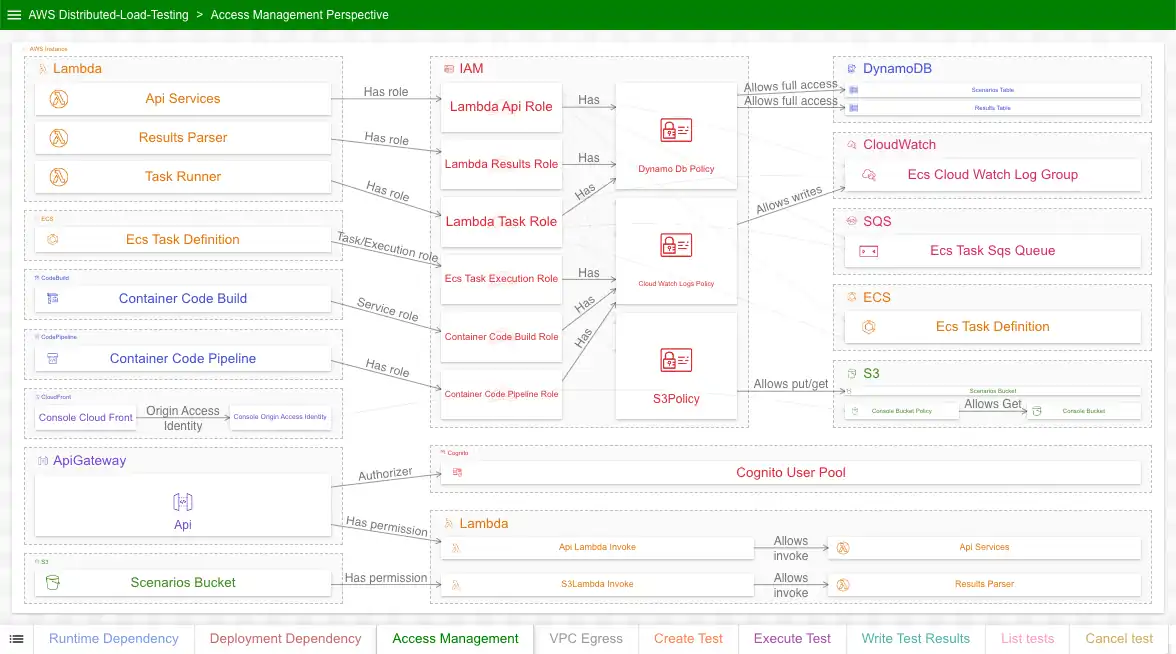
Perspective 3: Security and Access Management
Goal: Show which resources can access which resources, and how
Original
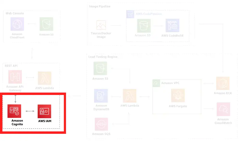
This perspective describes something the original doesn’t fully attempt to address: security and access management. For the solution to work, resources need to get data from, send data to, and sometimes (in the case of lambdas) invoke other resources. This is all managed through roles, policies, and permissions governed primary through IAM.
Obviously, this perspective goes into considerably more detail than the original diagram does. Like earlier, we can select individual resources to see what resources it can access and be accessed by (and how).
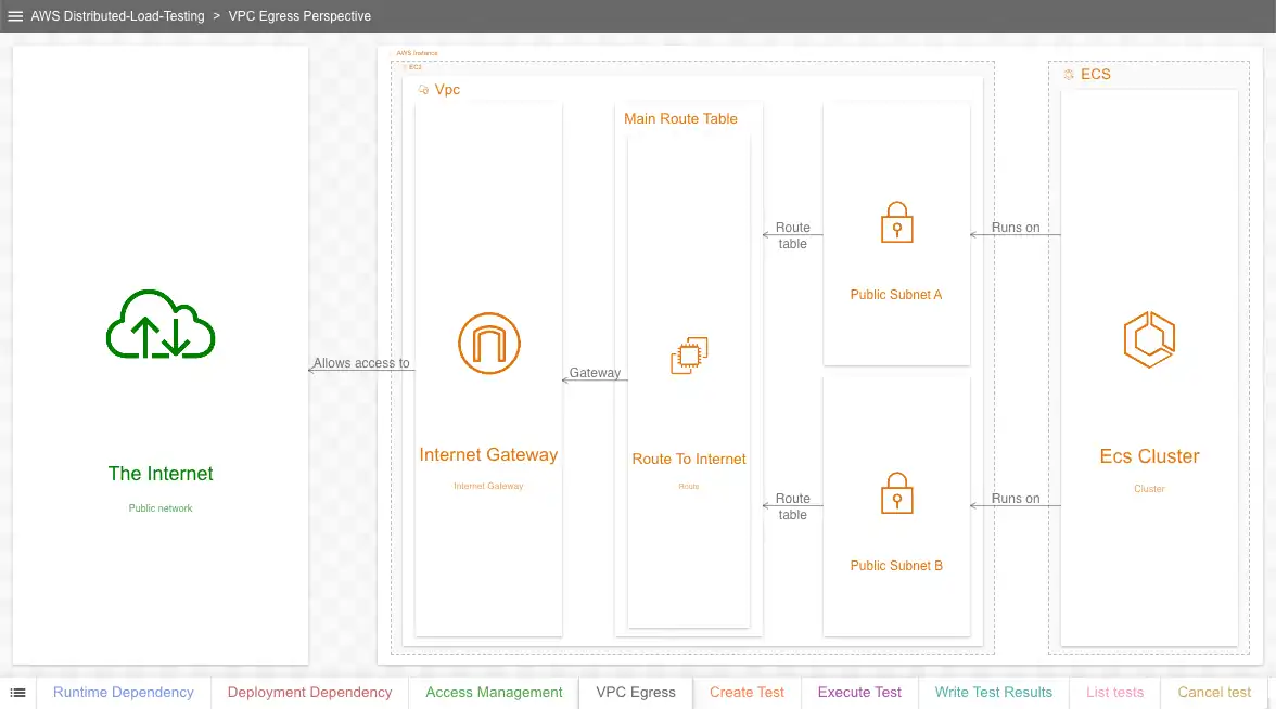
Perspective 4: VPC Egress
Goal: Show how VPC-based resources access the internet
Original
Naturally, the load testing cluster requires internet access to work. This simple diagram shows the resources allowing the cluster to access the internet from within the VPC.
Perspectives 5-9: Example control-flow sequences
Goal: Show detailed interactions between resources for common workflows
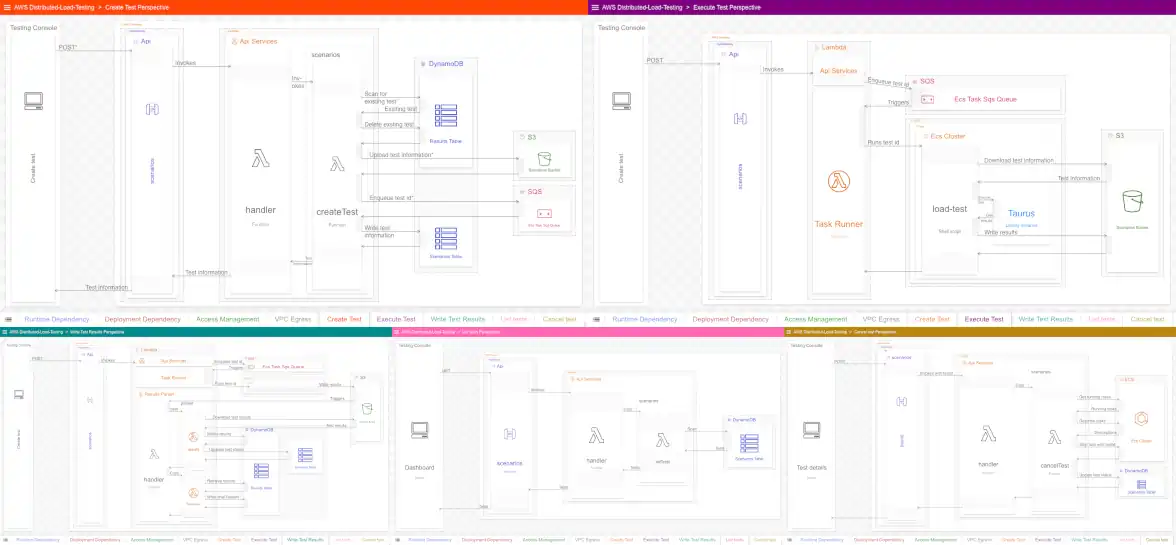
All of the previous perspectives are static perspectives. There is no notion of time; the relations they describe are continuously in effect. They do not have steps showing how the resources actually interact. To help the viewer better understand how the resources interact (and how complex those interactions can get), we include five sequence perspectives for this solution:
Create Test - Shows how new tests are created
Execute Test - Shows how new tests are executed after being created
Write Test Results - Shows how test results are written to DynamoDB
List tests - Shows how all running tests are fetched
Cancel Test - Shows how a running test is canceled
Other workflows that could be documented include getting individual tests and getting test results.
Conclusion
The conclusion of the previous entry listed guidelines for better architecture diagrams, all of which we followed here. We benefited greatly from breaking up the original diagram into multiple perspectives and using real resource names, for example. By making these and other improvements, we hopefully made this diagram much more useful as a technical resource.
If you haven’t already, click here to browse this diagram yourself. Questions or comments? Please reach out to me by email at billy@ilograph.com.


