

Concrete Diagramming Models, a Lightweight Alternative to C4

“All you have to do is write one true sentence. Write the truest sentence that you know.”
– Ernest Hemingway
This article introduces the concept of concrete diagramming models. It details what they are, how they’re created and used, and their benefits. It also compares and contrasts concrete diagramming models with C4 diagramming models.
What are diagramming models?
Model-based diagramming is a technique for bringing structure and consistency to technical system diagramming. Diagram models are essentially lists (or trees) of resources (things). An author then uses these resources when creating diagrams.
Diagram models are great for reuse. Diagram authors using a shared model can easily keep their diagrams in sync. Creating new diagrams from an existing model is also far more manageable than starting from scratch.
Diagram models are the diagramming equivalent of database schemas or static type checking. With some up-front investment, they help deliver system diagrams that provide long-term value.
Creating and using concrete diagramming models
There are different techniques and philosophies for creating diagramming models. The subject of this article is concrete diagramming models. Concrete diagramming models are bottom-up, fact-based models prioritizing hard information over generalizations. They are ideal for creating detailed diagrams, such as when diagramming existing systems.
Concrete diagramming models are domain-agnostic; they can be used to diagram any type of system. They are compatible with any diagramming tool; however, for best results, model-based diagramming tools are recommended over generic drag-and-drop tools.
Concrete and Abstract resources
Concrete models are so-named because they model a system starting with concrete resources. A resource is any discrete entity in a system that provides value; a concrete resource is material or tangible. It is an actual thing that indisputably exists. From computing, concrete resources can include the following:
| Database tables | Servers | |
| APIs | Pipelines | |
| Codebases | Repositories | |
| Packages | Executables | |
| People | Hardware |
| Resource Name | Resource Type | Color |
|---|---|---|
| getOrder | Lambda | Orange |
| createOrder | Lambda | Orange |
| getUser | Lambda | Orange |
| Orders | DynamoDB Table | Blue |
| Order History | DynamoDB Table | Blue |
| Users | DynamoDB Table | Blue |
| Order | API Resource | Purple |
| User | API Resource | Purple |
Diagramming with concrete resources
Creating diagrams with concrete resources is straightforward. Relationships between concrete resources are designated with arrows like so:
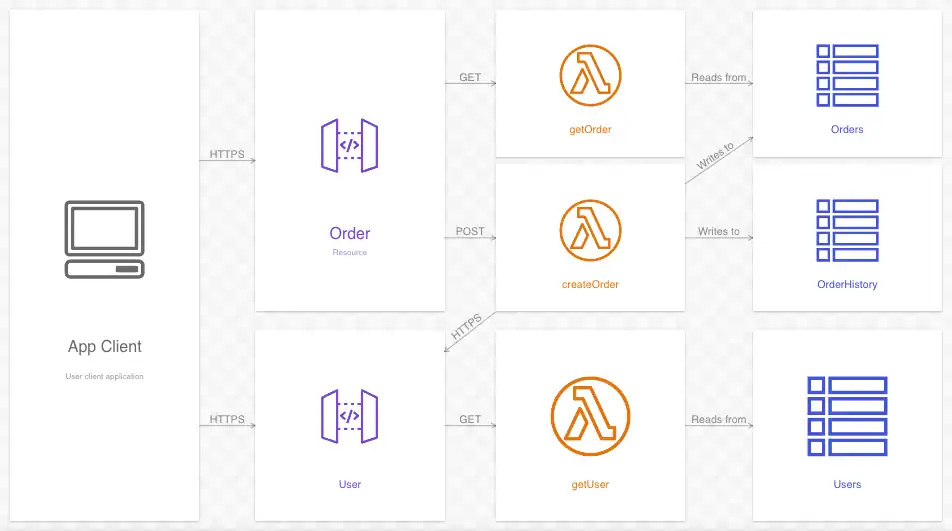
Multiple diagrams can be created using the model. Here is a sequence diagram showing the steps of a complex interaction between these same resources:
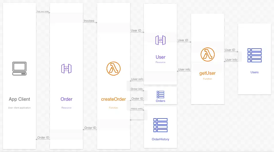
Toggling between these diagrams demonstrates they share a common model:
Composing concrete resources
In diagramming, resources can be composed (put inside one another). This helps organize the diagram and gives the viewer useful context. This diagram is the same as the sequence diagram in the previous section, only with composing resources:
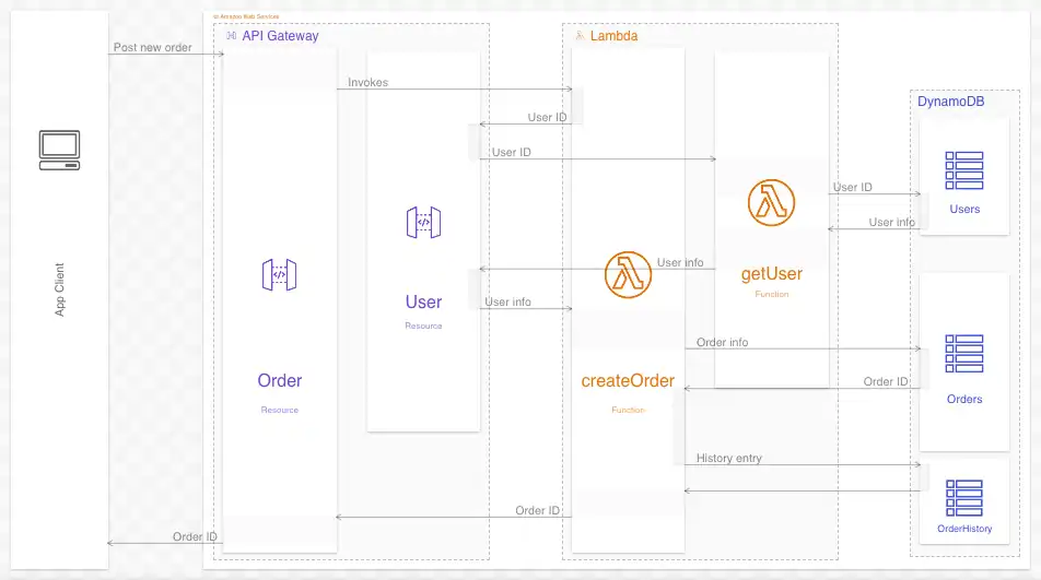
The newly-added composing resources are:
| Resource Name | Resource Type | Color |
|---|---|---|
| API Gateway | AWS Service | Purple |
| Lambda | AWS Service | Orange |
| DynamoDB | AWS Service | Blue |
| Amazon Web Services | Cloud Provider | Orange |
The addition of four composing resources gives the diagram more order. The viewer is also given important context about this system, namely the cloud provider (Amazon Web Services) and the services in that provider it uses (API Gateway, Lambda, and DynamoDB).
Additionally, these compositions can simplify a diagram. By zooming out and showing the only composing resources, high-level interactions are revealed:
As the above example demonstrates, any amount of composition is possible. Each “level” of detail simplifies the diagram until only the highest-level information is visible. In this example, at the highest level, the interaction is between only the client and AWS.
So far in these diagrams, every resource, even at the highest levels, is concrete. API Gateway, Lambda, DynamoDB are all real-life services, as are the individual resources (tables, Lambda, etc.). Sometimes, however, it is helpful to show resources composed in ways that aren’t strictly literal. This is done using abstract resources.
(Optional) Adding abstract resources
Concrete resources are the foundation of concrete models. Abstract resources play a secondary, and optional, part.
As noted previously, abstract resources are intangible and purely conceptual. For diagramming purposes, they exist only as compositions of many concrete resources. Unlike concrete resources, abstract resources do not convey information per se. Their value is in their ability to organize and simplify in conceptual ways.
Consider the sequence diagram in the previous section. It separates the database tables, Lambdas, and APIs into their respective AWS services. This is highly relevant, but not the only way to organize them. Somtimes (perhaps often) it is better to present them as services, like in the following diagram:
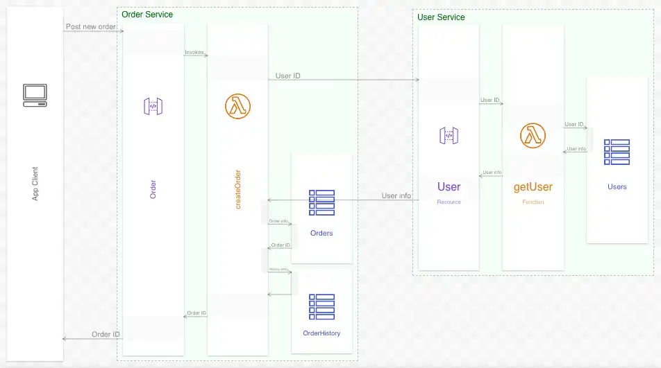
All of the interactions (arrows) are the same as before. Order Service and User Service (rendered in green) are the abstract resources. These services exist only conceptually; they are a convenient way of grouping APIs, Lambdas and database tables. Like concrete resources in the previous section, they can be used to demonstrate higher-level relations and interactions:
The benefits of using concrete diagramming models
The bottom-up, just-the-facts philosophy of concrete modeling offers essential benefits. It helps keep diagrams grounded in reality. Imprecise and untrue information is easier to spot, and can be rooted out sooner.
Concrete models do not rely on externally prescribed abstractions or concepts. They are adapted to a system, not the other way around. They describe systems using the language of the systems themselves.
As mentioned, concrete diagramming models are ideal for creating detailed diagrams and system documentation that delivers long-term value.
Concrete Modeling vs C4 Modeling
Concrete diagram modeling is an alternative to, but not a replacement of, the C4 Model created by Simon Brown.
What is C4?
Brown introduces the C4 Model as “an ‘abstraction-first’ approach to diagramming software architecture.” It prescribes “a set of hierarchical abstractions and a set of corresponding hierarchical diagrams.” These four prescribed levels of abstraction are Context, Container, Component, Code (hence C4).
The link above describes these abstractions and gives examples for each (“In the C4 model, a container represents an application or a data store”. Examples of “containers” in C4 include “Mobile apps”, “Databases”, and “File systems”). When modeling with C4, the modeler should map their resources to one of these four abstractions.
The C4 model is also top-down; it suggests that Context diagrams (the highest level) is a good starting point for diagramming as it allows the viewer to see the big picture.
Shortcomings of the C4 Model
The C4 Model is pretty well established, but it does have some shortcomings:
Opinionated abstractions
One of C4’s goals is to create a “ubiquitous language” to describe software systems. Diagram authors are tasked with mapping all of their resources to one of four levels of abstraction (Context, Container, Component, Code), and then use them in a handful of (also prescribed) diagram types. The thinking is that the industry gains long-term benefits by using a common language for abstraction in software diagramming.
The problem is that systems today have many different kinds of things. Servers, databases, virtualized containers, APIs, pipelines, repositories, packages, libraries, and (many, many) cloud resources are all concrete things that provide real value. Forcing them into one of C4’s four levels of abstraction doesn’t accomplish much. A database instance is a database instance; debating whether it is also a Container or a Component just isn’t worthwhile. Diagram authors and viewers are better off seeing these resources for what they actually are.
Further, when abstraction is required, domain-specific abstractions make more sense than arbitrary ones. Diagram authors benefit from thinking about each system on its own terms (and in its own terms), and diagram viewers do, too.
Abstraction blindness
Even when they’re a good fit, over-using abstractions can do harm. The top-down, abstraction-first approach of C4 risks focusing too much on a system’s abstractions at the expense of its concrete resources.
A system’s concrete resources, the actual things in a system, are almost always more important than the abstractions used to simplify them. So are the real-world relations and interactions between them. These are the resources diagram viewers most need to understand. Diagrams, and diagramming models, should focus on them as well. Only after doing the “hard” work of detailing these real-world resources should an author take the liberty of abstracting them away.
Concrete models and C4 Models
Both concrete models and C4 models have their place. They share the same goals of organization, consistency, and reuse in technical diagrams. C4 is top-down, opinionated, and abstraction-first. Concrete models are bottom-up, open, and concrete-first. Which to choose depends on one’s personal preference and diagramming goals.
Wrap up
Model-based diagramming is almost always the correct choice when creating diagrams with long-term value. Concrete diagramming models lean into this by emphasizing the real, value-producing resources in system diagrams. They are an excellent choice when the goal is to honestly inform the viewer, rather than merely make an impression.
Click here to view the diagram used throughout this article.
Share this article on Facebook
Share this article on LinkedIn